[2021-08-04 22:45:28] Meadow StdOut: Unhandled Exception: Meadow.Hardware.NativeException: Communication error. Verify device is powered and that SCL is Connected.
at Meadow.Hardware.I2cBus.DecipherI2CError (Meadow.Core.Interop+Nuttx+ErrorCode ec) <0xc0e3a5f8 + 0x0005a> in :0
at Meadow.Hardware.I2cBus.Write (System.Byte peripheralAddress, System.Span1[T] data) <0xc0e31a00 + 0x[2021-08-04 22:45:28] Meadow StdOut: 00be> in <d15b0c210aff4c3893b50c6dfd52aa0a>:0 at Meadow.Hardware.I2cPeripheral.WriteRegister (System.Byte address, System.Byte value) <0xc0e312c8 + 0x000d4> in <5dc1aab770164f6f8d47fd114196773f>:0 at Meadow.Foundation.ICs.IOExpanders.Is31fl3731.SelectPage (System.Byte page) <0xc0e31110 + 0x00014> in <b0d84ec33fdd479386d35f06b4404366>:0 at Meadow.Foundation.ICs.IOExpanders[2021-08-04 22:45:28] Meadow StdOut: Is31fl3731.WriteRegister (System.Byte frame, System.Byte reg, System.Byte data) <0xc0e310b8 + 0x0000a> in <b0d84ec33fdd479386d35f06b4404366>:0 at Meadow.Foundation.ICs.IOExpanders.Is31fl3731.Initialize () <0xc0e30ee0 + 0x00010> in <b0d84ec33fdd479386d35f06b4404366>:0 at ICs.IOExpanders.Is31fl3731_Sample.MeadowApp.Initialize () <0xc0e1c7b0 + 0x00046> in <55e89fe78d7948e883827[2021-08-04 22:45:28] Meadow StdOut: d07ffc3117>:0 at ICs.IOExpanders.Is31fl3731_Sample.MeadowApp..ctor () <0xc0823178 + 0x0000a> in <55e89fe78d7948e883827bd07ffc3117>:0 at ICs.IOExpanders.Is31fl3731_Sample.Program.Main (System.String[] args) <0xc0822e48 + 0x00034> in <55e89fe78d7948e883827bd07ffc3117>:0 [2021-08-04 22:45:28] Meadow StdErr: [ERROR] FATAL UNHANDLED EXCEPTION: Meadow.Hardware.NativeExcepti[2021-08-04 22:45:28] Meadow StdErr: on: Communication error. Verify device is powered and that SCL is Connected. at Meadow.Hardware.I2cBus.DecipherI2CError (Meadow.Core.Interop+Nuttx+ErrorCode ec) <0xc0e3a5f8 + 0x0005a> in <d15b0c210aff4c3893b50c6dfd52aa0a>:0 at Meadow.Hardware.I2cBus.Write (System.Byte peripheralAddress, System.Span1[T] data) <0xc0e31a00 + 0x000be> in :0
[2021-08-04 22:45:28] Meadow StdErr: t Meadow.Hardware.I2cPeripheral.WriteRegister (System.Byte address, System.Byte value) <0xc0e312c8 + 0x000d4> in <5dc1aab770164f6f8d47fd114196773f>:0
at Meadow.Foundation.ICs.IOExpanders.Is31fl3731.SelectPage (System.Byte page) <0xc0e31110 + 0x00014> in :0
at Meadow.Foundation.ICs.IOExpanders.Is31fl3731.WriteRegister (System.Byte frame, Syst[2021-08-04 22:45:28] Meadow StdErr: m.Byte reg, System.Byte data) <0xc0e310b8 + 0x0000a> in :0
at Meadow.Foundation.ICs.IOExpanders.Is31fl3731.Initialize () <0xc0e30ee0 + 0x00010> in :0
at ICs.IOExpanders.Is31fl3731_Sample.MeadowApp.Initialize () <0xc0e1c7b0 + 0x00046> in <55e89fe78d7948e883827bd07ffc3117>:0
at ICs.IOExpanders.Is31fl3731_Sa[2021-08-04 22:45:28] Meadow StdErr: ple.MeadowApp…ctor () <0xc0823178 + 0x0000a> in <55e89fe78d7948e883827bd07ffc3117>:0
at ICs.IOExpanders.Is31fl3731_Sample.Program.Main (System.String args) <0xc0822e48 + 0x00034> in <55e89fe78d7948e883827bd07ffc3117>:0
It looks like it cannot connect to the SCL, Meadow.Hardware.NativeException: Communication error. Verify device is powered and that SCL is Connected. at Meadow.Hardware.I2cBus.DecipherI2CError and I do not know if I have the wrong pins connected or I need those pull-out resistors to be connected to 3V3 or something. Any ideas?
I would try pull up resistors on the I2C clock and I2C data pins. Usually they’re built into the board but I’ve definitely come across I2C hardware that doesn’t include them.
It’s also worth checking the board for solder pads - sometimes they require a solder bridge to connect the resistors.
It did not work with 4.7kΩ resistors and i really wish that whoever wrote the example for the github would take an extra step to create a schematic [or something] in order to see which pins should be connected and if it requires anything extra, since it was testes with the real hardware in the time when the sample app for IS31FL3731 war written, was it? Taken a photo at that time would be sufficient.
then one more question,
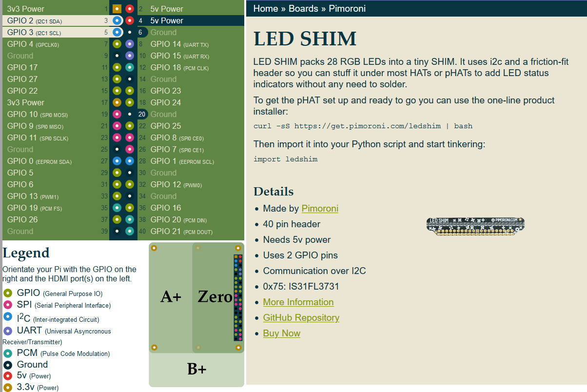
what is 0x74? why is it this exact value for the I2C address? Could it be changed? Is it constant for every Is31fl3731?