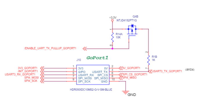
I found this is Netduino Archive. I am wondering if this is correct.
Courtesy: JerseyTechGuy
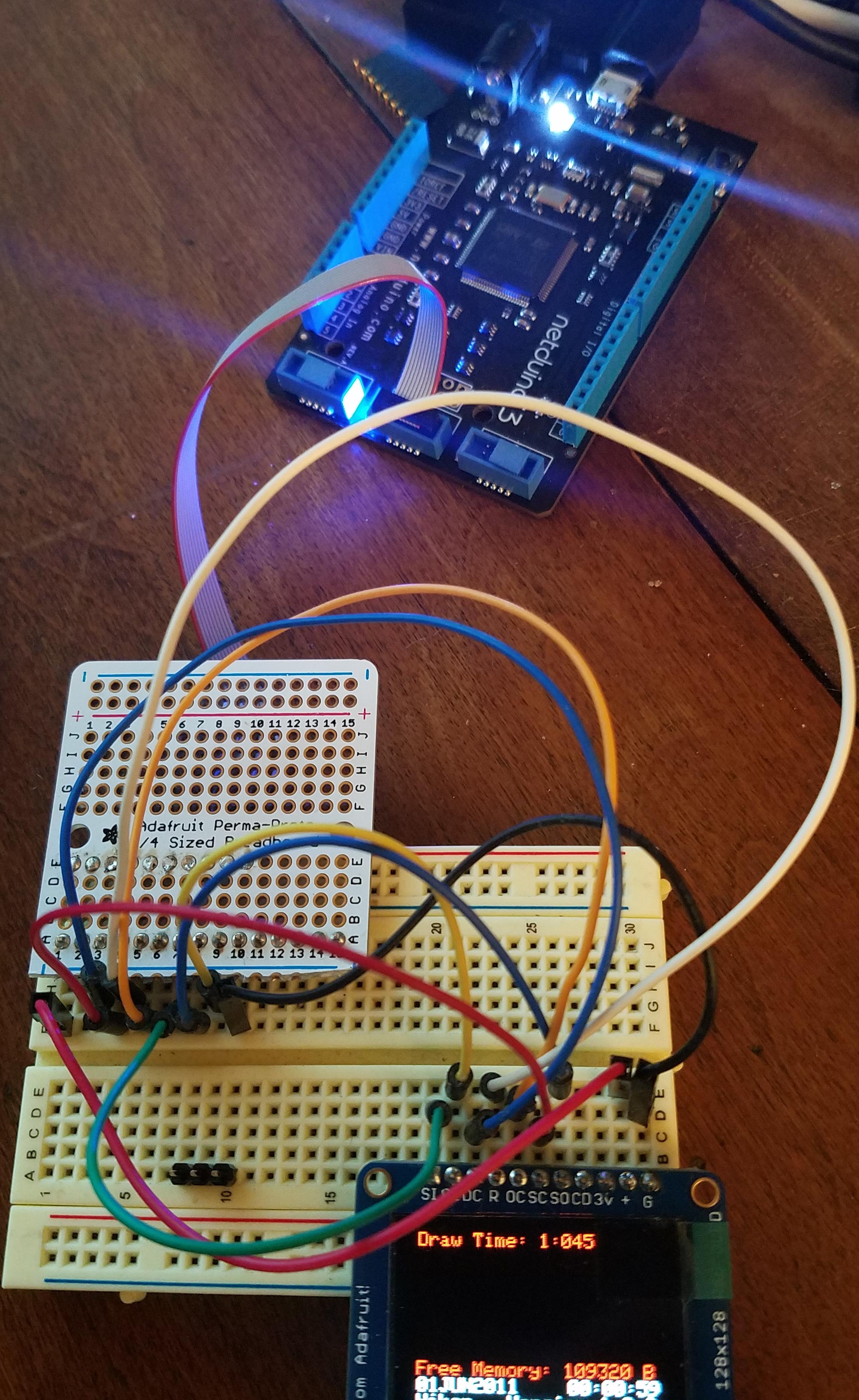
Nice work! I like the design of the board and the silk layer. Makes it easy to know which type of Gadgeteer modules work where.
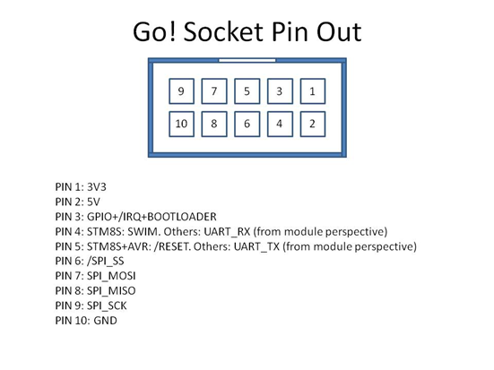
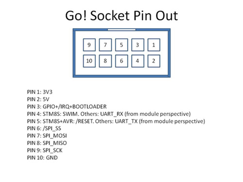
For anyone who doesn’t know much about the Gadgeteer modules I found this chart useful:
A - Three analog inputs, with pins number 3 and 4 doubling as general-purpose input/output. In addition, pin number 6 is a general-purpose input/output, and pin number 3 supports interrupt capabilities.
I - I2C interface. Pins 8 and 9 are the dedicated I2C data (SDA) and clock (SCL) lines. Note that a mainboard should include pull-up resistors for these pins, in the region of 2.2K Ohms. Modules must not include their own pull-ups on these lines. In addition, pins 3 and 6 are general-purpose input/outputs, with pin 3 supporting interrupt capabilities.
K - UART (serial line) interface operating at TTL levels, with hardware flow control capabilities. Pin 4 (TX) is data from the mainboard to the module, and pin 5 (RX) is data from the module to the mainboard. These lines are idle high (3.3V), and can double as general-purpose input/outputs. Pin 6 (RTS) is an output from the mainboard to the module, indicating that the module may send data. Pin 7 (CTS) is an output from the module to the mainboard indicating that the mainboard may send data. The RTS/CTS are ‘not ready’ if high (3.3V) and ‘ready’ if low (0V). In addition, pins 3 is a general-purpose input/output, supporting interrupt capabilities.
U - UART (serial line) interface operating at TTL levels. Pin 4 (TX) is data from the mainboard to the module, and pin 5 (RX) is data from the module to the mainboard. These lines are idle high (3.3V), and can double as general-purpose input/outputs. In addition, pins 3 and 6 are general-purpose input/outputs, with pin 3 supporting interrupt capabilities.
O - Analog output on pin 5. In addition, pins 3 and 4 are general-purpose input/outputs, and pin 3 includes interrupt capabilities.
P - Three pulse-with modulated (PWM) outputs on pins 7, 8 and 9. Pins 7 and 9 double as GPIOs. In addition, pin 3 is an interrupt-capable GPIO, and pin 6 is a GPIO.
S - Serial peripheral interface (SPI). Pin 6 is the chip-select (CS) line, pin 7 is the master-out/slave-in (MOSI) line, pin 8 is the master-in/slave-out (MISO) line, and pin 9 is the clock (SCK) line. In addition, pins 3, 4 and 5 are general-purpose input/outputs, with pin 3 supporting interrupt capabilities.