I’ve got a small project going that requires some form of wireless communication. I’ve got a few old SeeedStudio Bluetooth shields, and figured I’d just use those. But, here’s my problem, I’ve got another shield working which requires I2C, and when stacked on the board by itself, everything works smoothly. As soon as I plug in the Bluetooth shield things get hinky. I2C sometimes works, sometimes appears not to, but almost always is astoundingly slow. I’m assuming that the issue is power, does anyone have any suggestions for resolving this? At the moment I’m powering the device from USB, and haven’t tried another supply, though if it is power, I’m cautious about providing a higher rated supply at risk of pushing through too much current.
Is there a way to identify if I’ve simply got some kind of brownout condition?
Would it be worth my time considering a move to WiFi or BLE connections instead, or am I still going to run into the issue?
That doesn’t sound like a power issue.
What bluetooth shield are you using? is it using I2C? Does it have anything wired to I2C?
The boards are the old Seeedstudio Bluetooth V1.1 shields. It is the same one described here: http://forums.netduino.com/index.php?/topic/9000-netduino-and-bluetooth/
I didn’t think it was I2C, you can see that it’s only got 8&8 headers on the digital I/O side, so I was thinking that it doesn’t have any impact there, since the N+2 exposes those on pins that don’t exist for this board. But, now that I’m looking at the silk screen here:
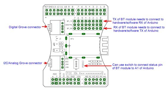
I’m seeing that one of those “grove” connectors is marked I2C, but it appears to be mapped to A4/A5. I’m not sure what traffic would be on A4/A5 otherwise, so I cannot image that’s an issue, but now I’m really curious.
I2C pins on Arduinos are on pins A4/A5, if memory serves, the original Netduinos also put I2C on those pins.
Most of the Bluetooth boards I have seen use a COM port to communicate with the Bluetooth module. They expose an AT command set to the allow control of the module. The post you link to suggests that serial comms is being used for the Bluetooth board. actually, just followed the link to the product page, it’s a UART interface.
Do you have equipment to allow you to work out if the application is slow or if the I2C comms is slow? Thinking scope or logic analyser to work out when the comms starts / stops.
Regards,
Mark
Thanks all,
Unfortunately, I’ve not got a scope or logic analyzer. Actually I’ve probably misspoken somewhat, yes, it is a UART interface, and I’m using the COM1 on the N+2. I’ve got the BT board working 100% using the published AT command set, when it is alone, and the I2C interface shield working just fine by itself. Now they just need to learn to work together. I’ve verified that there’s not any shared pins between the two boards, so I’m still a bit stumped.
After looking into it a bit I suspect that I’ve left A4 and A5 floating, and as you’ve mentioned, it was designed for an Arduino pre-R3. I’m waiting to get to the house to try it out, but I suspect that maybe I’ve got some induced signal floating around when both are installed, and I’ve already verified that the other shield is tied between SDA/SCL and A4/A5. So the real question for the moment, is what are the steps to bring those low? And if they are low, is that going to short the signal that’s intended to get to the SDA/SCL pins?
SDA and SCL should have pull up resistors installed as he lines should be high when they are not in use. The microcontroller does not do this. For single devices, a 4K7 resistor is the approximate go to value to try first.
How did you determine that the I2C interface was slower when the two boards were connected?
Regards,
Mark
The shield does have pull-up resistors on the SDA and SCL pins, but since those pins are tied over to A4/A5 and they are floating, I’m thinking that I may need to pull those up as well. It might help to know the I2C board is the Adafruit Motor Shield V2. (Maybe I need to set it a 3v logic…)
Originally I was scratching my head about what was happening, but then I noticed that the I2C board functions weren’t working, but the serial communication was. The serial comms are happening in a separate thread, so I simply moved my thread start to below where the I2C comms start, and I simply never get there. As soon as I remove the shield with the BT hardware, I hit the breakpoint in seconds.
I’ve just had a look at the schematic for the Adafruit Motorshield 2.2 and to be honest I would expect the pullups to work as the two pairs of lines for SDA/SCL and A4/A5 are connected. You say they are floating, it’s difficult to see that without a scope.
In terms of logic levels, yes, I would change SJ1 (according to the schematic I have seen, may vary for your board) if necessary to work with 3.3V logic levels.
You mention that I2C and BT both work on their own. Have you tried putting the two boards on the Netduino at the same time and executing an application with just the I2C code and see if that still works. Then repeat but this time an application with just the BT code? Sorry if I’m asking the obvious but I may not be aware of all of the combinations you have tried.
Regards,
Mark
Mark and Bryan, thanks for the help. I finally got this working. I had to break out some other I2C devices and start working back through all my code to see what the heck is going on. I grabbed several sensors, two of which have pull up resistors on the boards, and one which did not. I was having absolutely no luck, until I got to the one that I had to wire in some pull-ups, which worked flawlessly. I started to suspect that may be the issue, and sure enough I wired in the pull-ups in the other sensors and data started moving.
I put everything back together, and sure enough once I wired in some pull up resistors (to 5v not 3v3, by the way) on my original package I had data moving.
So I guess now the question is why the heck am I having to add additional pull up resistors? From everything I’m seeing it should just work when they are on the boards. I suspect that I’m doing something wrong, but I’ve not got the foggiest clue what.
Again, guys, thanks for the feedback.
If you want more information on how I2C works with respect to pull-up resistors then this is a realy good article:
Regards,
Mark