GoBus / GoPort Cables?

I found this is Netduino Archive. I am wondering if this is correct.

Courtesy: JerseyTechGuy

Nice work! I like the design of the board and the silk layer. Makes it easy to know which type of Gadgeteer modules work where.

For anyone who doesn’t know much about the Gadgeteer modules I found this chart useful:

A - Three analog inputs, with pins number 3 and 4 doubling as general-purpose input/output. In addition, pin number 6 is a general-purpose input/output, and pin number 3 supports interrupt capabilities.

I - I2C interface. Pins 8 and 9 are the dedicated I2C data (SDA) and clock (SCL) lines. Note that a mainboard should include pull-up resistors for these pins, in the region of 2.2K Ohms. Modules must not include their own pull-ups on these lines. In addition, pins 3 and 6 are general-purpose input/outputs, with pin 3 supporting interrupt capabilities.

K - UART (serial line) interface operating at TTL levels, with hardware flow control capabilities. Pin 4 (TX) is data from the mainboard to the module, and pin 5 (RX) is data from the module to the mainboard. These lines are idle high (3.3V), and can double as general-purpose input/outputs. Pin 6 (RTS) is an output from the mainboard to the module, indicating that the module may send data. Pin 7 (CTS) is an output from the module to the mainboard indicating that the mainboard may send data. The RTS/CTS are ‘not ready’ if high (3.3V) and ‘ready’ if low (0V). In addition, pins 3 is a general-purpose input/output, supporting interrupt capabilities.

U - UART (serial line) interface operating at TTL levels. Pin 4 (TX) is data from the mainboard to the module, and pin 5 (RX) is data from the module to the mainboard. These lines are idle high (3.3V), and can double as general-purpose input/outputs. In addition, pins 3 and 6 are general-purpose input/outputs, with pin 3 supporting interrupt capabilities.

O - Analog output on pin 5. In addition, pins 3 and 4 are general-purpose input/outputs, and pin 3 includes interrupt capabilities.

P - Three pulse-with modulated (PWM) outputs on pins 7, 8 and 9. Pins 7 and 9 double as GPIOs. In addition, pin 3 is an interrupt-capable GPIO, and pin 6 is a GPIO.

S - Serial peripheral interface (SPI). Pin 6 is the chip-select (CS) line, pin 7 is the master-out/slave-in (MOSI) line, pin 8 is the master-in/slave-out (MISO) line, and pin 9 is the clock (SCK) line. In addition, pins 3, 4 and 5 are general-purpose input/outputs, with pin 3 supporting interrupt capabilities.

I think the answer is - it depends :slight_smile:

What I would do is:

  1. Grab the schematic and the datasheet for the STM32 chip on the board you have.
  2. From the schematic work out which STM32 pins are connected to each of the Go Port pins.
  3. Cross reference this with the STM32 datasheet. This should give you the pins and the capabilities of the pin. I would have thought GPIO would be a minimum capability for the UART/SPI pins.
  4. Next up, create a test application and try to create an InputPort or OutputPort. Note that when you do this you will have to use Cpu.Pins and not Pins to reference the pin on the STM32. Also remove any reference to GoBus in the project References.

Sounds like an interesting experiment…

Regards,
Mark

Had a play to see what would happen, not a lot of luck.

Some more digging required.

Regards,
Mark

I also was digging… since I am waiting on cables to get here I thought I would at least try turning on the GoPort LED’s…

        var goPortLedPins = new[] { 40, 42, 45 };
        var goPorts = new ArrayList();
        for (int i = 0; i < goPortLedPins.Length; i++)
        {
            var port = new OutputPort((Cpu.Pin)goPortLedPins[i], false);
            goPorts.Add(port);
        }
        Thread.Sleep(1000);
        foreach (OutputPort outputPort in goPorts)
        {
            outputPort.Write(true);
        }
        Thread.Sleep(1000);
        foreach (OutputPort outputPort in goPorts)
        {
            outputPort.Write(false);
        }

This did not work. I removed all GoBus references, (and even tried removing SecretLabs (when will this change to Wilderness?) one at a time until I was only left with MS namespaces.

I’ve resorted to downloading the Netduino source… ugh, maybe some pointers on setting this all up so that I can edit what I need to, compile, etc… There is a lot of code to go through. I’ve already downloaded the MDK (5.10 as suggested)

-IdleGoose

Ok, here is something I find strange. I noticed that when I try and toggle GoPort 3 LED (pin 45 per the schematic) the main PWR LED toggles… so either there is a miss-mapping on the schematic or something else fishy is going on. Confirmed by doing this on 2 separate N3’s (plain)

        var led = new OutputPort((Cpu.Pin) 45, false);

        while (true)
        {
            led.Write(true);
            Thread.Sleep(1000);
            led.Write(false);
            Thread.Sleep(1000);
        }

@bryancostanich

I tried to figure out how the pin IDs are mapped so I wrote a short application to prove the mapping. I was not able to turn on the GOPort 1 LED. If my mapping is correct it would map to pin PE9 that has a ID of 73?

Imports Microsoft.SPOT
Imports Microsoft.SPOT.Hardware
Imports SecretLabs.NETMF.Hardware
Imports SecretLabs.NETMF.Hardware.Netduino
Imports System
Imports System.Net
'**For file system
Imports System.IO

Module Module1
Structure sPINS
Dim PinName As String
Dim PinID As Integer
End Structure

Dim Netduino3Pins(79) As sPINS

Sub Main()

    Dim PINMap(79) As String

    For i = 0 To 79
        If i < 16 Then
            PINMap(i) = "PA" & i.ToString
            Netduino3Pins(i).PinName = PINMap(i)
            Netduino3Pins(i).PinID = i
        End If

        If i > 15 Then
            If i < 32 Then
                PINMap(i) = "PB" & (i - 16).ToString
                Netduino3Pins(i).PinName = PINMap(i)
                Netduino3Pins(i).PinID = i
            End If
        End If

        If i > 31 Then
            If i < 48 Then
                PINMap(i) = "PC" & (i - 32).ToString
                Netduino3Pins(i).PinName = PINMap(i)
                Netduino3Pins(i).PinID = i
            End If
        End If

        If i > 47 Then
            If i < 64 Then

                PINMap(i) = "PD" & (i - 48).ToString
                Netduino3Pins(i).PinName = PINMap(i)
                Netduino3Pins(i).PinID = i
            End If
        End If

        If i > 63 Then
            PINMap(i) = ("PE" & (i - 64).ToString)
            Netduino3Pins(i).PinName = PINMap(i)
            Netduino3Pins(i).PinID = i
        End If
        Debug.Print("Pin Name " & Netduino3Pins(i).PinName & " Pin ID: " & Netduino3Pins(i).PinID)

    Next

    Debug.Print("Netduino Pins.GPIO_PIn_D0 maps to the STF4.. Processor as " & Pins.GPIO_PIN_D0.ToString)
    Debug.Print("Pin Name: " & Netduino3Pins(Pins.GPIO_PIN_D0).PinName)

    ' Debug returns
    ' Netduino Pins.GPIO_PIn_D0 maps to the STF4.. Processor as pin ID 39
    ' Pin Name : PC7

    ' To set pin DO to an output the following lines do the same 
    ' Dim PinD0 = New OutputPort(DirectCast(39, Cpu.Pin), True)
    ' Dim PinD0 = New OutputPort(Pins.GPIO_PIN_D0, True)

    ' This is correct looking at the schematic https://github.com/WildernessLabs/Netduino_Hardware/blob/master/N3_WiFi/N3_WIFI_13DEC16_0800.pdf

    ' To set the main LED on for 3 seconds
    Dim LED = New OutputPort(DirectCast(10, Cpu.Pin), False)
    LED.Write(True)
    Thread.Sleep(3000)
    LED.Write(False)

    ' The GoBus LED is connected to PE9 
    ' The PE9 ID is 73
    '******This doesn't work
    ' Will cause an error

    ' Dim GO1LED = New OutputPort(DirectCast(73, Cpu.Pin), False)
    ' led.Write(True)
    '  Thread.Sleep(3000)
    ' led.Write(False)


End Sub

End Module

Thanks @David_Weaver. Where did you find out that the pin ID’s start with “PA”? I was using the physical layout per ST. This helps but I would still like to have full control over the GoPorts, or at least have them be usable. Going to try out a few more things before I attempt to edit/recompile firmware. If the only thing that doesn’t work is the LED I could get by, going to check the SPI, CS, and other pins in the mean time.

-IdleGoose

Update: No Luck. I assume they are “In Use” and not able to be freed without recompiling. So begins my next adventure. Post pending on setting up Keil 5 and other stuff.

This is the schematic on github.com with the pins labeled. I hope if you get the issue figured out you will post the solution.

I had the same (minus wifi) schematic… I did not realize the pins were not mapped to the physical(chip/die) location. All of the pins seem to be locked. Going to look at the GoBus code and see how they override that… If I can find it.

Thanks IdleGoose good work!

I was going by the pin numbers on the schematic as well. There looks to be a mapping of the ports to pin numbers in STM32_GPIO_functions.cpp in the SDK.

Regards,
Mark

The issue with pin 73 is in the firmware for Netduino 3 I successfully used this code on a Netduino 2 board without an error. However there is nothing mapped to it.

Dim GO1LED = New OutputPort(DirectCast(73, Cpu.Pin), False)
GO1LED.Write(True)
Thread.Sleep(3000)
GO1LED.Write(False)

I found this in the IO_Init.cpp (source). Sections D and E are enabled but no settings, I have tried a few experiments with section D & E to no avail.

void __section(SectionForBootstrapOperations) BootstrapCode_GPIO() {

    /* Enable GPIOA, GPIOB, GPIOC, and GPIOD clocks */
    RCC->AHB1ENR |= RCC_AHB1ENR_GPIOAEN | RCC_AHB1ENR_GPIOBEN | RCC_AHB1ENR_GPIOCEN | RCC_AHB1ENR_GPIODEN;
#if defined(PLATFORM_ARM_Netduino3) || defined(PLATFORM_ARM_Netduino3Ethernet) || defined(PLATFORM_ARM_Netduino3Wifi)
    RCC->AHB1ENR |= RCC_AHB1ENR_GPIOEEN;
#endif

    GPIOA->MODER = 0xA8000000;
    GPIOB->MODER = 0x00000280;
    GPIOC->MODER = 0x00A00000;
    //GPIOD->MODER = 0x00002A80;

	GPIOA->OTYPER = 0x00000000; // default to push-pull (default state)
	GPIOB->OTYPER = 0x00000000;
	GPIOC->OTYPER = 0x00000000;
	//GPIOD->OTYPER = 0x00000000;

    GPIOA->OSPEEDR = 0x00000000;
    GPIOB->OSPEEDR = 0x000000C0;
    GPIOC->OSPEEDR = 0x00A00000;
    //GPIOD->OSPEEDR = 0x00002A80;

    GPIOA->PUPDR = 0x64000000;
	GPIOB->PUPDR = 0x00000100;
    GPIOC->PUPDR = 0x00000000;
    //GPIOD->PUPDR = 0x00000000;

	STM32_GPIO_AFConfig(0x08, 2); // NOTE: check to see if this is really necessary to disable pin 8 MCO

#if defined(PLATFORM_ARM_Netduino3Ethernet) || defined(PLATFORM_ARM_Netduino3Wifi)
	// optionally...turn on SD card power automatically
        CPU_GPIO_EnableOutputPin(0x11, FALSE); // PB1: /PWR_CTRL_MICROSD
#endif
}

WAHOO!!! Cannot believe it was something this easy… Tonight I will write a more in-depth test, but for now I am going to treat myself to a dinner.

            Port.ReservePin((Cpu.Pin)78,false);

            var led = new OutputPort((Cpu.Pin)78, false);

            while (true)
            {
                led.Write(true);
                Thread.Sleep(1000);
                led.Write(false);
                Thread.Sleep(1000);
            }

Update: Totally works. Will work on some code this week and have a helper class for next weekend. Going to test COM port later as well.

1 Like

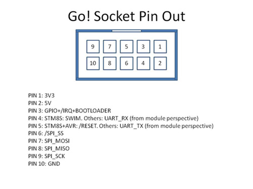
I connected a serial device to COM5. COM5 maps to PD8 (id 56) and PD9(id 57) . On GoPort1 I connected the device to pins 1,4,5,10. I diidn’t use the Port.ReservePin command.

It Worked!

The Pin mapping is below:

Pin Name PA0 Pin ID: 0
Pin Name PA1 Pin ID: 1
Pin Name PA2 Pin ID: 2
Pin Name PA3 Pin ID: 3
Pin Name PA4 Pin ID: 4
Pin Name PA5 Pin ID: 5
Pin Name PA6 Pin ID: 6
Pin Name PA7 Pin ID: 7
Pin Name PA8 Pin ID: 8
Pin Name PA9 Pin ID: 9
Pin Name PA10 Pin ID: 10
Pin Name PA11 Pin ID: 11
Pin Name PA12 Pin ID: 12
Pin Name PA13 Pin ID: 13
Pin Name PA14 Pin ID: 14
Pin Name PA15 Pin ID: 15
Pin Name PB0 Pin ID: 16
Pin Name PB1 Pin ID: 17
Pin Name PB2 Pin ID: 18
Pin Name PB3 Pin ID: 19
Pin Name PB4 Pin ID: 20
Pin Name PB5 Pin ID: 21
Pin Name PB6 Pin ID: 22
Pin Name PB7 Pin ID: 23
Pin Name PB8 Pin ID: 24
Pin Name PB9 Pin ID: 25
Pin Name PB10 Pin ID: 26
Pin Name PB11 Pin ID: 27
Pin Name PB12 Pin ID: 28
Pin Name PB13 Pin ID: 29
Pin Name PB14 Pin ID: 30
Pin Name PB15 Pin ID: 31
Pin Name PC0 Pin ID: 32
Pin Name PC1 Pin ID: 33
Pin Name PC2 Pin ID: 34
Pin Name PC3 Pin ID: 35
Pin Name PC4 Pin ID: 36
Pin Name PC5 Pin ID: 37
Pin Name PC6 Pin ID: 38
Pin Name PC7 Pin ID: 39
Pin Name PC8 Pin ID: 40
Pin Name PC9 Pin ID: 41
Pin Name PC10 Pin ID: 42
Pin Name PC11 Pin ID: 43
Pin Name PC12 Pin ID: 44
Pin Name PC13 Pin ID: 45
Pin Name PC14 Pin ID: 46
Pin Name PC15 Pin ID: 47
Pin Name PD0 Pin ID: 48
Pin Name PD1 Pin ID: 49
Pin Name PD2 Pin ID: 50
Pin Name PD3 Pin ID: 51
Pin Name PD4 Pin ID: 52
Pin Name PD5 Pin ID: 53
Pin Name PD6 Pin ID: 54
Pin Name PD7 Pin ID: 55
Pin Name PD8 Pin ID: 56
Pin Name PD9 Pin ID: 57
Pin Name PD10 Pin ID: 58
Pin Name PD11 Pin ID: 59
Pin Name PD12 Pin ID: 60
Pin Name PD13 Pin ID: 61
Pin Name PD14 Pin ID: 62
Pin Name PD15 Pin ID: 63
Pin Name PE0 Pin ID: 64
Pin Name PE1 Pin ID: 65
Pin Name PE2 Pin ID: 66
Pin Name PE3 Pin ID: 67
Pin Name PE4 Pin ID: 68
Pin Name PE5 Pin ID: 69
Pin Name PE6 Pin ID: 70
Pin Name PE7 Pin ID: 71
Pin Name PE8 Pin ID: 72
Pin Name PE9 Pin ID: 73
Pin Name PE10 Pin ID: 74
Pin Name PE11 Pin ID: 75
Pin Name PE12 Pin ID: 76
Pin Name PE13 Pin ID: 77
Pin Name PE14 Pin ID: 78
Pin Name PE15 Pin ID: 79

This is a link to the Hardware Provider source code:

Ok, next issue I’ve run into. The display module I use also has an SD card attached. When I try to mount with

_csPin = GoSocket2.RxPin; //71 _spi= GoSocket2.SPI; //Spi4 _rootName = "SD"; //Also tried @"SD\" StorageDevice.MountSD(_rootName, _spi, _csPin);

I get a System.IO.Exception
ErrorCode VolumeNotFound System.IO.IOException.IOExceptionErrorCode

I can use this card in a N+2 so I wonder if this is a limitation of the pin, although this pin says IO per ST. Perhaps have to figure out how to use blockStorage underlying code.

I’m not terribly worried about it as this would just add another feature, but it would be a nice feature.

-IdleGoose

IdleGoose

I had the same issue with the Netduino 2 Plus board. I am designing a custom board that requires a SD card and an a ESP8266 WiFi module testing my drivers on the Netduino 2 Plus card that I turned into a Netduino2.

This is how I did it.

Follow the instructions here starting at the line “To Flash the firmware”.
http://forums.netduino.com/index.php?/topic/8116-netduino-plus-2-firmware-v422-update-2/

Next use MFDeploy to update to the Netduino 2 4.3 firmware.

You will need to use the Hardware Provider assemblies for the Netduino3 card you are using.

I don’t know if this will work on the Netduino 3 but it may be worth a try?

If you need the 3100 WiFi or the Ethernet I would not do it.

If the process above doesn’t work you should be able to return the board to it’s previous state following Chris Walker’s instruction from a previous post.

To manually flash firmware using ST DFUSE tools, grab the latest copy of ST’s DFUSE tools from the download link at the bottom of the following page:
http://www.st.com/we...SS1533/PF257916

To erase your board’s firmware (do this first):

  1. Detach your Netduino
  2. Press and hold your Netduino’s pushbutton while plugging it in via USB; this will put it in bootloader mode.
  3. Erase the firmware on your Netduino using the STDFU Tester application

a. Select the “Protocol” tab
b. Press the “Create from Map” button
c. Select the “Erase” radio button option
d. Press the “Go” button
e. Wait for erase process to complete

To create the DFU files which you will program onto your Netduino:

  1. Run “DFU File Manager” (from the ST DFU tools)
  2. Select “I want to GENERATE a DFU file” and press OK.
  3. Click “S19 or HEX…” and then select one of the firmware files in Netduino Update’s respective Firmware folder.
  4. Click the “generate” button to generate a DFU file which contains the S19 (HEX) file you picked in step 3.
  5. Click “delete selected image”.
  6. Repeat steps 3-5 for the other two firmware files.

Finally, flash each of the .DFU files using the ST DfuSe Demonstrator application (included with STDFU Tester).

  1. Run “ST DfuSe Demonstrator”
  2. Locate the “Upgrade or Verify Action” pane (bottom-right pane)
  3. Press “Choose…” and select one of the generated DFU files
  4. Check the “Verify after download” option
  5. Press “Upgrade”. It will take a few moments to update your Netduino.
  6. Repeat steps 3-5 for the other two firmware files.

I don’t want to flash to a N2 or N+2, I am using a N3 which do not even use the same chip. If anything the pin maps to the GoSockets are not on the N2 Firmware. I have not put any new firmware on the board, although I do plan on on updating to 4.4 at some point. I plan on digging deeper into this over the weekend… After I can build the firmware, no sense in altering the firmware if I can’t compile it. Thank you for the the posting, I will be sure to add that to my firmware post for oopsies.

-IdleGoose

I don’t know how much mapping is done in the firmware or in the hardware provider? I was able to use the hardware provider files and the firmware even though the boards use different processors. The Netduino 2 uses the Cortex M3 and the Netduino 2 plus uses the Cortex M4. I guess in a perfect world you could use the Netduino 2 firmware and the Netduino 3 hardware provider assembly ???

If you see any code that does not require the Secret Labs Netduino IO Assembly I would like to use it with your 4.4 update when done.